Lately I get a lot of small packages with hardware modules from China. They take between 2 and 6 weeks to arrive. Some of the parts I’m waiting for are needed to continue my current project(s). Because of this I often check the mailbox and it is really annoying to open an empty mailbox. Therefore, I was building the mailbox notification.
Hardware
I checked the WIFI inside the mailbox and it was not existing so I couldn’t just use a simple ESP8266 like the Wemos D1 Mini and a battery to get it to work. Instead I decided to order a 433 MHz radio frequency (RF) transmitter module and combine it with a very low power ATtiny85 that I can program with Arduino.
Hardware parts
| Part | Price |
|---|---|
| 433 MHz radio frequency (RF) transmitter module | 1.00 € |
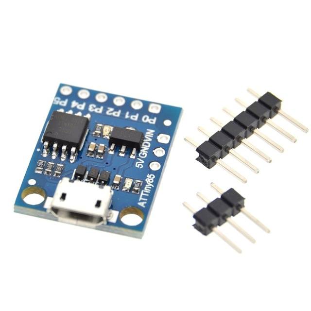
| ATtiny85 Digispark | 1.20 € |
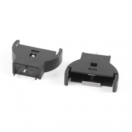
| Battery coin socket (don’t buy a no name product from China!) | 1.29 € |
| CR2032 button cell battery | 0.22 € |
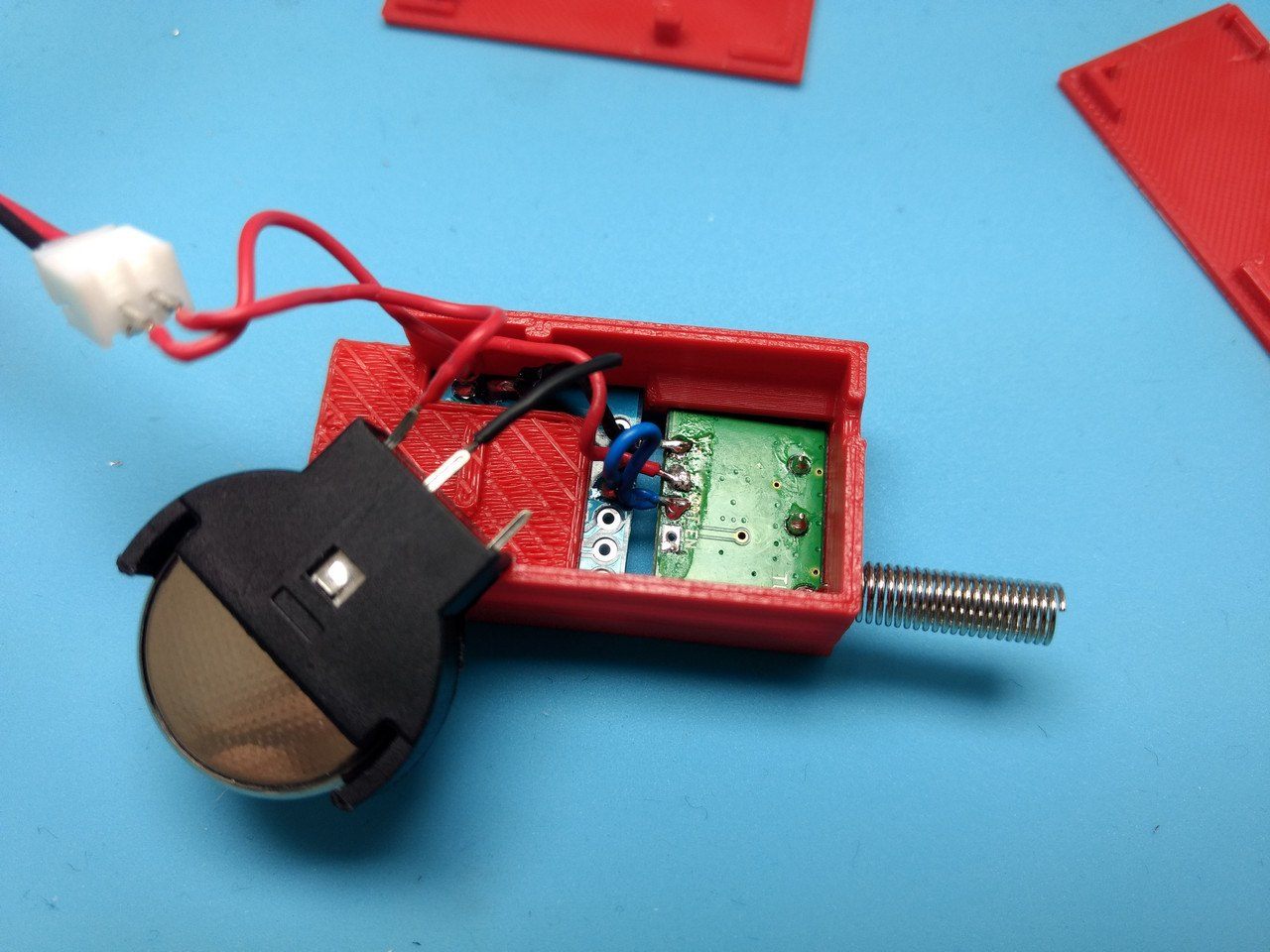
Hardware pictures

Software
First, we need to flash a new firmware onto the ATtiny85 since the stock firmware is outdated and - more importantly - waits 5 secs before booting to allow an easy program code upload. For me it was important to get rid of the 5 sec bootup since my solution cuts the power of the ATtiny85 completely as long as the postbox lit is not open. The few seconds it is open will be enough to bootup and send a notification!
ATtiny85 firmware
To upgrade the firmware I followed the GitHub article from Ircama. Basically, you need to:
- Install (Windows) USB drivers
- Get the latest source code of the Micronucleus bootloader
- Change the firmware configuration for the ATtiny85 by defining the
ENTRYMODEtoENTRY_EXT_RESET. This prevents the 5 sec waiting time on startup. You can reset the ATtiny85 by connectingP5andGNDwith a 100R resistor. - Build the new firmware
- Create upgrade firmware - the ATtiny85 has not enough space for a complete firmware update so you need to generate a firmware upgrade instead of replacing the whole thing.
- Flash the new firmware
Arduino transmitter
The code I flashed on my ATtiny85 is very small. As soon as the ATtiny85 starts it will send the notification 15 times - to make sure it gets received - and then the ATtiny85 goes to sleep in case the postbox stays open and the power is not cut off.
I use a CR2032 button battery to power the ATtiny85. This battery outputs only 3V and the ATtiny85 is used to 5V. To get him to work with a 3V battery we need to downgrade the CPU speed by using the Digispark (1mhz - No USB) profile in the Arduino IDE. The No USB option only means that you can’t reach the USB port inside your code - using the USB port to flash a code update or use the default Digispark (Default - 16.5mhz) profile is not a problem.
#include <RCSwitch.h>
#include <avr/sleep.h>

RCSwitch mySwitch = RCSwitch();

void setup() {
  // Send notification 15 times
  mySwitch.enableTransmit(2); // 2 is P2
  mySwitch.setRepeatTransmit(15);
  mySwitch.send("011100000110001001100001"); // pba = Post Box Alert = 7365217

  // Shutdown device
  set_sleep_mode(SLEEP_MODE_PWR_DOWN); // sleep mode is set here
  sleep_enable();
  sleep_mode();
}

void loop() {  }
Arduino receiver
The following code I used to test the transmitter. I connected the receiver (included in the hardware parts) to a Wemos D1 Mini. It has a ESP8266 WIFI microchip and support the serial monitor. This way you can monitor what you receive. You will also receive signals from other devices since 433 MHz is a common frequency for garage doors.
#include <RCSwitch.h>

RCSwitch mySwitch = RCSwitch();

void setup() {
  Serial.begin(115200);
  pinMode(BUILTIN_LED, OUTPUT);
  mySwitch.enableReceive(13);   // Receiver on interrupt GPio 13 => that is pin D7
  Serial.print("Starting up.. ");
}

void loop() {
  if (mySwitch.available()) {

    Serial.print("Received ");
    Serial.print( mySwitch.getReceivedValue() );
    Serial.print(" / ");
    Serial.print( mySwitch.getReceivedBitlength() );
    Serial.print("bit ");
    Serial.print("Protocol: ");
    Serial.println( mySwitch.getReceivedProtocol() );

    mySwitch.resetAvailable();

    digitalWrite(BUILTIN_LED, LOW);
    delay(500);
    digitalWrite(BUILTIN_LED, HIGH);
  }
}
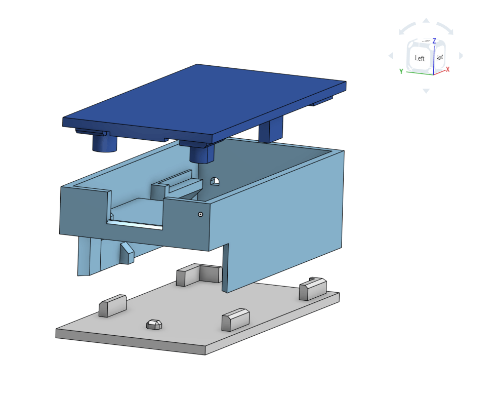
3D printed case
I created a custom 3D case model with Onshape, a CAD online service to get the smallest possible containment for the hardware. I have attached the STL files for you to download in the footer 1 2 3 but I recommend to export the latest version from Onshape directly.
Assembly
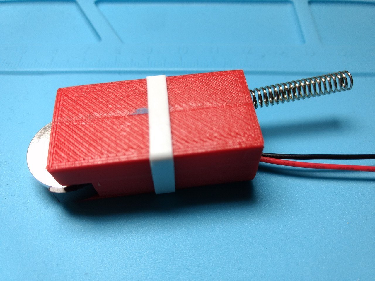
Installation
Connecting the two wires that go out of the case will boot the ATtiny85 and transmit the notification. The Installation is depending on your postbox. I have a type A postbox. Therefor I have soldered a reed switch (normally closed - NC) to the wires. I mounted a magnet on the inside of the postbox lid and the reed switch next to it. As long as the lid is closed the magnet will be next to the reed switch and there is no connection. As soon as someone opens the lid the magnet will move away from the reed switch and the ATtiny85 gets powered up.
If you have a type B postbox you could use a normally closed switch that is often used in wardrobes. Mount it next to the lid and the ATtiny85 will power up as soon as the lid is open.
Backend
To receive the notification, I use a Wemos D1 Mini with the receiver attached. The Wemos is running the OpenMQTTGateway software that sends the received 433MHz signal via the MQTT protocol to my Home Assistant software that is running on my server. And finally I have configured Home Assistant to use Pushbullet to notify me on my phone.