This project creates a system that can run an ARM Linux server 24/7 without any external power. The system will run on batteries that are charged by a solar panel. A remote monitoring solution will track the system and collect sensor data.
The initial data collection will focus on the system performance:
- solar power output
- battery levels
- system power consumption
- temperature and moisture inside the case
Bill of materials
Most of the parts were already present from other projects. In case all the parts need to be ordered the bill will be around 150€ (without shipping). But it can also be much cheaper if you do not use the convenient prototype boards and shields.
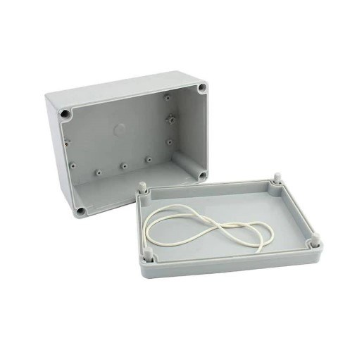
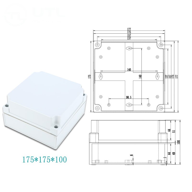
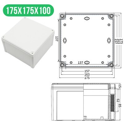
- 13€ Electrical Junction Box IP67 Waterproof, 175x175x100
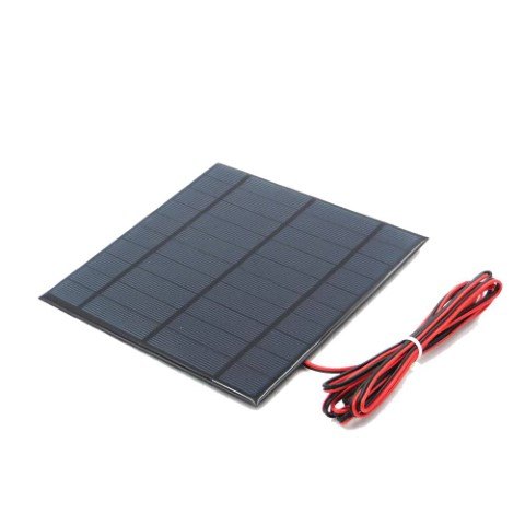
- 10€ Solar Panel 5V, 840mA, 165x165
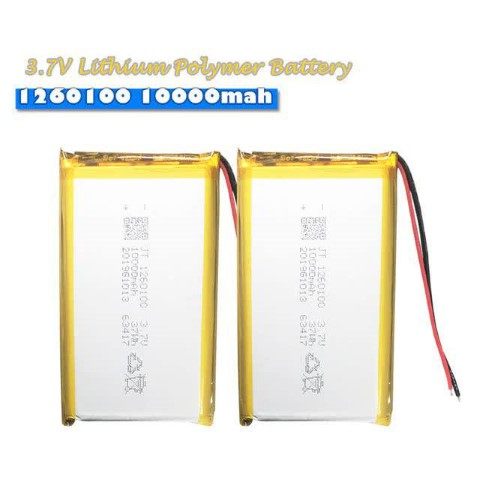
- 14€ 2x 10000mAh Lipo cells
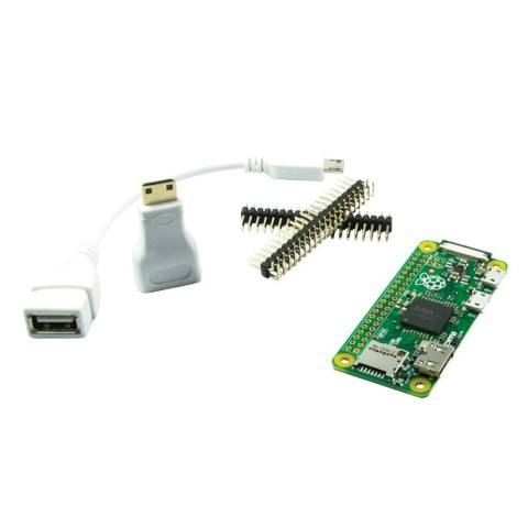
- 14€ Raspberry Pi Zero (no WIFI) and tools
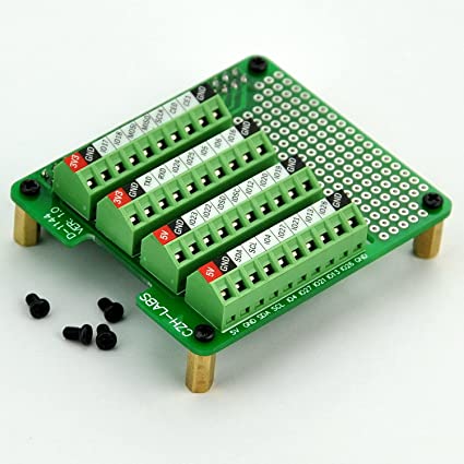
- 20€ Screw terminal
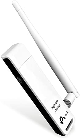
- 8€ WIFI USB card TL-WN722N
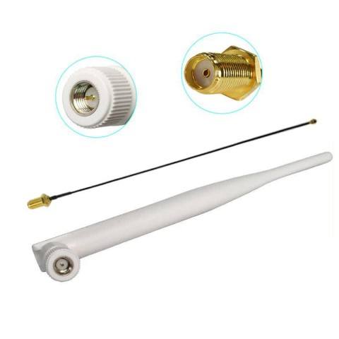
- 2€ WIFI Antenna 2.4Ghz, 5dbi
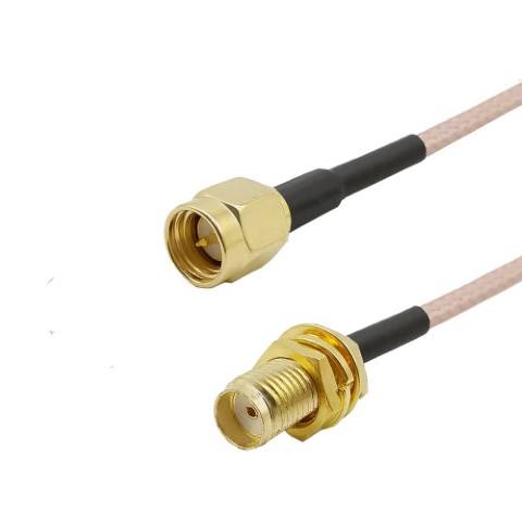
- 2€ SMA Pigtail
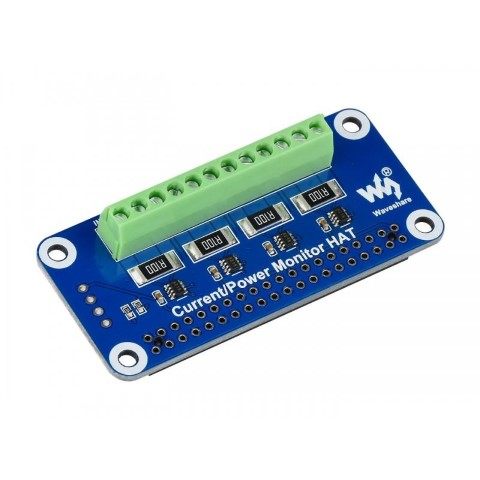
- 12€ Current/Voltage/Power Monitor
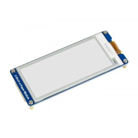
- 17€ E-Ink display module 296x128, 2.9inch
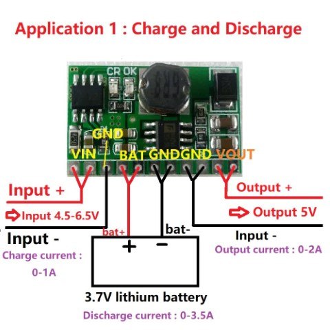
- 4€ UPS mobile power board 5V/2.1A
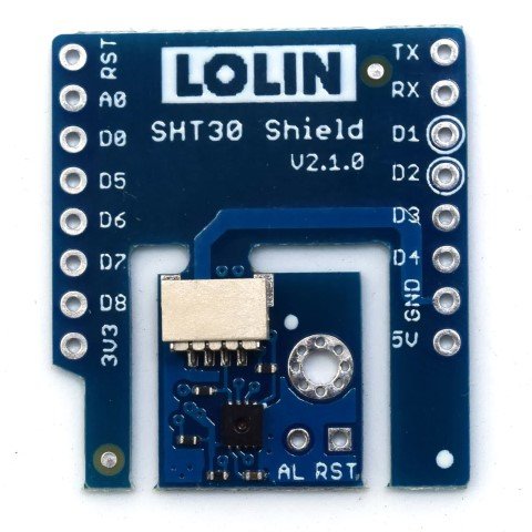
- 4€ Temperature and humidity sensor SHT30, I2C
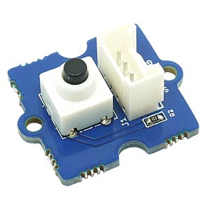
- 2€ Button
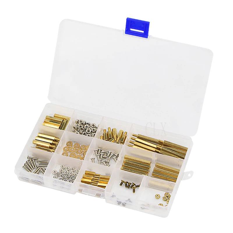
- 10€ Hex spacer screws M2.5/M3
- 8€ Ribbon cable 40 pin
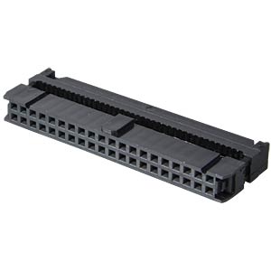
- 2€ 2x 40 pin socket
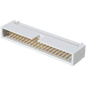
- 0€ 40 pin plug
- 12€ Foam insulator, self adhesive


3D Model
The 3D models are made in Fusion 360. The source file1 as well as the STL files of the battery level2 and the electronics level3 can be found at the bottom of the post. The latest versions can be found in the GitHub repository that will be published with the second part of the series.
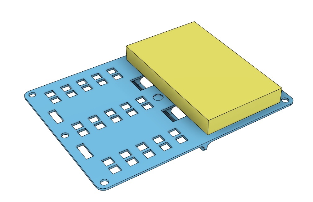
The 3D model of the battery grill has a spacer in the middle to allow air ventilation from below. This is not necessary when mounting the two batteries with Velcro (instead of zip ties) since the Velcro tape will already create enough space between battery and the battery grill. In this case the insolation can be placed closer to the battery grill.
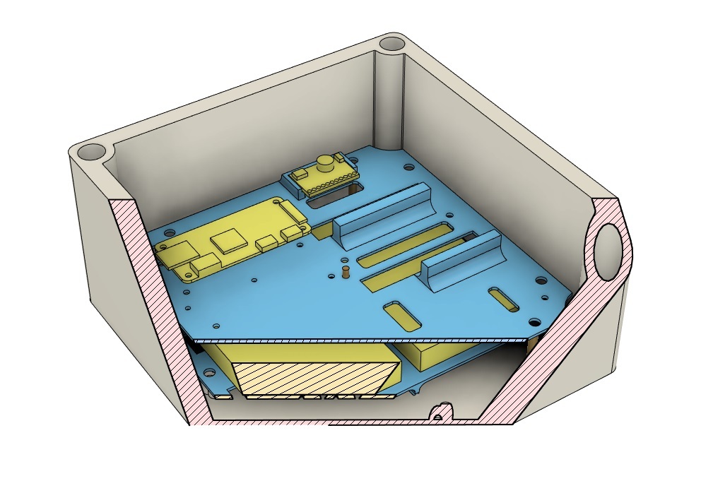
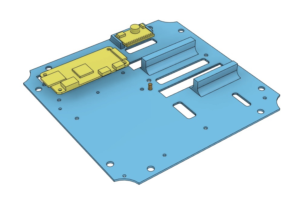
The 3D model of the electronics level has holes for the 40-pin sockets. The modules (hats) will be connected by a 40-pin ribbon cable that will be mounted at the bottom of the plate. The two standoffs in the picture are supporting the modules since the 40-pin sockets are preventing mounting screws. The rest of the wholes are for fasteners and cable outlets.
The Raspberry Pi as well as the modules will be fastened by hex spacer screws. One spacer screw will be mounted at the bottom of the electronics level to increase steadiness.
Since some components can be scavenged from other projects (button and sensors) it is hard to add specific mounting holes that are flexible enough to accommodate the different dimensions. For this reason, the model does not include holes for all components. These components will be mounted with the use of a glue gun.
Next
In the next part of the series we will assemble the parts, take care of the wiring and setup the scripts.